
A few years ago I started slowly transforming my house into a "Smart House".
It started with some friends of ours showing us their smart bulbs and how they could tell Alexa to turn them on and off. I'll admit, I was skeptical of how smart bulbs could be life changing, and it took a few years until I would get there.
But this isn't that story, this is about how I converted my plain ol' dumb fan into a Wi-Fi enabled smart fan for my OpenHab system. If you aren't familiar with OpenHab I'll be writing up a blog post about it and my system in a while. The tl;dr is that it lets you control your smart home rather than being locked into a service or hardware provider. But be weary, it's not for everyone - the high level of flexibility and control comes with a high level of technical aptitude.
This will be a multi-part entry. Part 1 (this part) will cover creating a custom Wi-Fi (not ZWave or ZigBee - just Wi-Fi) binding for my smart fan and a start to an Arduino sketch to allow controlling the fan. Part 2 will carry on from there, completing the Arduino sketch and hooking up the controller to the fan. At some point I may combine these into a single blog entry which was my original intent but it just started taking too long and I don't want to forget everything I've done for Part 1.
Building the Smart Fan "Brain"
For these types of guides, I'm always going to provide the exact list of components I use. There's two reasons for this, first, whenever I run across guides it always seems like people forget to list their components. This makes it extremely difficult to repeat their build. Second, I'm using affiliate links when possible - I don't and won't put ads on my website but affiliate links are innocuous to the end consumer.
Materials
The brain is pretty simple and all of the parts, combined, cost less than $10. Well, sort of, I bought 5x packs of Mini's and Displays at a combine cost of ~$40. You can buy individuals but these things are so useful it's nice to have extra on hand. Let's have a quick look at the BOM:
- Lasko High Velocity Tower Fan (or your fan)
- WeMos D1 Mini (~$3/board)
- I2C OLED Display (not necessary; ~$3.50/display)
The Fan
The fan doesn't really matter. Not for the controller logic of the smart fan. It will matter in Part 2 when we start integrating the brain with the fan itself as we'll need a way to determine and control the fan's state. But most fans should be able to be controlled. It's just a matter of figuring out how.
For this post, I'll be integrating with our Lasko fan that we use when we sleep for "white noise" and air circulation. For what it's worth, it's a great fan and blows very well. Unfortunately, it also sucks because the power button resets if the device loses power - thus I can't just use a smart switch or outlet to turn it on/off.
WeMos D1 Mini
This D1 Mini is a "WeMos" compatible board - which is to say it's not the original "LOLIN" board. It uses the ESP8266 Wi-Fi chip which features a full TCP/IP stack so you can dive right into the IOT life. It's specs are pretty sweet:
- 11 digital IO, interrupt/pwm/I2C/one-wire supported(except D0)
- 1 analog input(3.2V max input)
- a Micro USB connection
- Compatible with MicroPython, Arduino, nodemcu
All five of my boards worked on arrival but some reviewers weren't so lucky. One thing I'll point out, with most of these kits, sensors, actuators, etc, the documenation and printed labels aren't necessarily always accurate. For example, some OLED I²C displays show SCK/SDA versus SCL/SDA (the write pins for I²C). These types of discrepencies might be the reason some "components" don't work. That or the hardware is just bad - that happens a lot too.
I²C OLED Display
You don't need a display but developing your own hardware is a lot more rewarding when you have instantaneous feedback (you know, like software). Not to mention, these displays are cheap so you might as well just have a few around. It's uses I²C (Inter-Integrated Communication) to talk with the D1 Mini which means it only use up two pins versus SPI's (Serial Peripheral Interface) four pins. That'll make a difference when we get to reading the fan's state (more on that in Part 2).
This display is small so you might look at grabbing something bigger depending on your application. With that said, it is perfect for these types of small controller applications so if you're smartifying a fan and you don't want to spend an arm and a leg, pick some of these up.
That's basically it for Part 1 but we'll probably need a few more things for Part 2. I'll update this list when we get there but it's probably not going cost more than a few dollars for the rest of the components.
OpenHab - The IOT "Hub"
OpenHab is an awesome piece of software that abstracts away nearly all of the complexities of controlling your smart devices. One of those abstractions are bindings:
A binding is an extension to openHAB that integrates an external system like a software service or a hardware device. The external system is represented as a set of Things and sometimes Bridges with Channels.
Well, that sounds like exactly what we need!
OpenHab is currently in version 3 as of writing this article. My OpenHab system runs OpenHab2 which supports version 1 and version 2 bindings. For this article, I'm going to focus on writing an OpenHab2 binding (because that's what I'm using). However, I'm reasonably confident the binding will work with OpenHab3 (although they are deprecating version 1 support with 3) and they've provided a detailed guide on migrating version 2 bindings to version 3.
Let's get started.
Creating Your Custom Binding
OpenHab3 introduces a nice shell script to create a templated out binding. Unfortunately, that doesn't exist in the latest OpenHab2 tag so we get to do it the ol' fashioned way - copying an existing one.
I should note, you could use the OpenHab3 script to create your binding and then convert it back to an OpenHab2 variant. That's probably possible but I wasn't able to get it to work. That was before finding the detailed guide on the conversion and I'm sure I missed a couple things.
First thing's first, let's get our development environment set up:
# Install JDK11
brew tap adoptopenjdk/openjdk
brew install --cask adoptopenjdk11

# Install Maven 3.X
brew install maven@3.5
export PATH="/usr/local/opt/maven@3.5/bin:$PATH" >> ~/.zshrcOk, cool, let's grab the code:
# Clone the OpenHab2 Addons repo (you might fork it yourself)
git clone -b 2.5.12 git@github.com:berdon/openhab-addons.git
export JAVA_HOME=`/usr/libexec/java_home -v 11.0.10`And, finally, let's copy some existing Addon. There's a lot, you could pick any, I chose the Autelis binding.
cd openhab-addons
cp -R bundles/org.openhab.binding.autelis bundles/org.openhab.binding.someidentifier
There's a few i's and t's to dot and cross:
- Add
/bundles/org.openhab.binding.someidentifier @youtoCODEOWNERS - Add a
<dependency>block for your binding tobom/openhab-addons/pom.xml - Add a
<module>block for your binding tobundles/pom.xml - Find and replace all instances of
org.openhab.binding.auteliswithin your binding and replace it withorg.openhab.binding.someidentifier
And with that you should be ready to go! Now, before we do too much else, let's consider some of our options for communicating with our custom controller.
IoT Communication
There are a small number of standard ways most devices use for discovery and communication:
- Z-Wave
- ZigBee
- Wi-Fi
Z-Wave is a mesh-network based protocol using a ~800-900 MHz band for communication with a range of 30-100m and supports up to 232 devices per network. It's been sold to various companies and is a closed protocol.
ZigBee is also a mesh-network based "specification" but uses a 2.4 GHz band so it could potentially conflict with Wi-Fi networks. It supports up to 65,000 devices and ranges of 75-300m. It's an open specification defined in IEEE 802.15.4.
Wi-FI...can either use something like SSDP (Simple Service Discovery Protocol) via something like UPnP or...anything else you want. Given the practically limitless possibilities of socket communication, TCP/IP, etc, you could just about do whatever you want.
But it's a lot faster to stand on the shoulder of giants so we'll just use SSDP/UPnP for discovery and then Rest-ish HTTP endpoints for communication. Not to mention if you want to use Z-Wave or ZigBee we'd need to buy this chip that we can interface with the D1 Mini and that just adds more cost, complexity, etc. It's maybe not a terrible idea because then you can just use the ZigBee Binding for OpenHab but then you get to spend an extra $10, miss out on learning something, and let's not forget you need a Z-Wave or ZigBee hub. Trade-offs trade-offs...
Either way, you're reading what I did and I chose to use Wi-Fi. Though I might write something later about interfacing with the Gowoops CC2530 because I do have a ZigBee hub (Raspberry Pi + ZigBee dongle) and I did already buy them...
Let's look at setting up a discoverable SSDP device on the D1 Mini.
Getting Started With the D1 Mini
First, make sure you have the Arduino IDE. It's a little buggy and...weird but it gets the job done.
Next, you'll want to install the "esp8266" boards in your board manager:
- Tools -> Boards -> Board Manager
- Search for "esp8266"
- It will be the one by the "ESP8266 Community"
- Click Install
Now go to to Tools -> Boards and select the "WeMos D1 Mini" which opens up a broad set of file menus allowing you to select various libraries specific to the D1 Mini. Huzza!
Making a Discoverable "Thing"
It's super simple, actually. There is a Wi-Fi library and an SSDP library you can add that covers basically everything for you.
You can see a sample sketch of using SSDP by going to File -> Examples -> ESP8266SSDP -> SSDP. That will open up a tab with a new complete sketch that looks a whole lot like:
#include <ESP8266WiFi.h>
#include <ESP8266WebServer.h>
#include <ESP8266SSDP.h>

#ifndef STASSID
#define STASSID "your-ssid"
#define STAPSK  "your-password"
#endif

const char* ssid = STASSID;
const char* password = STAPSK;

ESP8266WebServer HTTP(80);

void setup() {
  Serial.begin(115200);
  Serial.println();
  Serial.println("Starting WiFi...");

  WiFi.mode(WIFI_STA);
  WiFi.begin(ssid, password);
  if (WiFi.waitForConnectResult() == WL_CONNECTED) {

    Serial.printf("Starting HTTP...\n");
    HTTP.on("/index.html", HTTP_GET, []() {
      HTTP.send(200, "text/plain", "Hello World!");
    });
    HTTP.on("/description.xml", HTTP_GET, []() {
      SSDP.schema(HTTP.client());
    });
    HTTP.begin();

    Serial.printf("Starting SSDP...\n");
    SSDP.setSchemaURL("description.xml");
    SSDP.setHTTPPort(80);
    SSDP.setName("Philips hue clone");
    SSDP.setSerialNumber("001788102201");
    SSDP.setURL("index.html");
    SSDP.setModelName("Philips hue bridge 2012");
    SSDP.setModelNumber("929000226503");
    SSDP.setModelURL("http://www.meethue.com");
    SSDP.setManufacturer("Royal Philips Electronics");
    SSDP.setManufacturerURL("http://www.philips.com");
    SSDP.begin();

    Serial.printf("Ready!\n");
  } else {
    Serial.printf("WiFi Failed\n");
    while (1) {
      delay(100);
    }
  }
}

void loop() {
  HTTP.handleClient();
  delay(1);
}So what's exactly happening in the above code? Let's break it down:
- Lines 1-3 include the various "libraries" we need to set up a Wi-Fi connection and create an SSDP device
- Lines 5-11 set up our Wi-Fi particulars
- Lines 20-22 connect to your Wi-Fi
- Lines 24-31 create a HTTP web server that hosts the necessary routes to answer SSDP/UPnP requests
- Lines 33-44 set up the SSDP particulars
- Lines 55-58 ensure that new HTTP requests are handled
We have what we need to create a discoverable device and host a web server to handle arbitrary requests. But what are we doing with those OLED displays?
Using an OLED Display
Turns out those are super simple to use too! Let's go to Tools -> Library Manager and find and install "ESP8266 and ESP32 OLED driver for SSD1306" displays by "ThingPulse, by Fabrice Weinberg".
Then you can see a sample sketch by going to File -> Examples -> ESP8266 and ESP32 OLED driver for SSD1306 displays -> SSD1306SimpleDemo. The demo is a bit too complex to include here but the useful bits are:
// Libraries for the display
#include <Wire.h>               // Only needed for Arduino 1.6.5 and earlier
#include "SSD1306Wire.h"        // legacy: #include "SSD1306.h"

// The I2C OLED Interface
SSD1306Wire display(0x3c, SDA, SCL);

void setup() {
  // Initialising the UI will init the display too.
  display.init();
  display.flipScreenVertically();
  display.setFont(ArialMT_Plain_10);

  // Display some text
  display.setTextAlignment(TEXT_ALIGN_LEFT);
  display.drawString(0, 0, "Hello world");
}

void loop()
{
}
All in all, not too complicated. We include the libraries we need, instantiate a display OLED interface variable, and call some setup routines to get the display ready.
Believe it or not that's all the building blocks we need to build a simple fan controller.
Getting Started with Discovery
Let's start with the a "shell" of a discoverable (using SSDP) device:
#include <ESP8266WiFi.h>        // WiFi
#include <ESP8266WebServer.h>   // HTTP Web Server
#include <ESP8266SSDP.h>        // UPnP/SSDP
#include <Wire.h>
#include "roboto_mono_light.h"  // Font
#include "SSD1306Wire.h"        // OLED Display

#ifndef STASSID
#define STASSID "your-ssid"
#define STAPSK  "your-password"
#endif

const char* ssid = STASSID;
const char* password = STAPSK;

// The I2C OLED Interface
SSD1306Wire display(0x3c, SDA, SCL);

// Handle for the WebServer
ESP8266WebServer HTTP(80);

// WiFi connectivity state
bool wifiConnected = false;

/**
 * DisplayText
 */
void UpdateOLEDDisplay(const char* message)
{
  display.clear();
  display.setTextAlignment(TEXT_ALIGN_LEFT);
  display.drawStringMaxWidth(0, 0, 128, message);
  display.display();
}

/**
 * Initializes:
 *  - Serial
 *  - OLED Display
 *  - WiFi connection
 *  - HTTP WebServer
 *  - UPnP/SSDP
 */
void setup() {
  // Initialize our serial output
  Serial.begin(9600);

  InitializeDisplay();

  Serial.println();
  Serial.printf("Connecting to WiFi...");
  UpdateOLEDDisplay("Connecting...");

  // Connect to WiFi
  WiFi.mode(WIFI_STA);
  WiFi.begin(ssid, password);
  if (WiFi.waitForConnectResult() == WL_CONNECTED) {
    Serial.printf("Done\n");
    UpdateOLEDDisplay("Connecting...Done");
    wifiConnected = true;

    InitializeWebServer();
    InitializeSSDP();
  }
  else
  {
    Serial.printf("WiFi Failed\n");
    UpdateOLEDDisplay("Connecting...Failed");
    while (1)
    {
      delay(100);
    }
  }
}

/**
 * Initialize the display and set the font.
 */
void InitializeDisplay()
{
  // Initialising the UI will init the display too.
  display.init();

  display.flipScreenVertically();
  display.setFont(Roboto_Mono_Light_Small);
}

/**
 * Initialize the HTTP WebServer, setup the available routes
 * AND, the bulk of the work, rig the routes to their respective
 * fan controller business logic.
 */
void InitializeWebServer()
{
  Serial.printf("Starting HTTP WebServer...");
  UpdateOLEDDisplay("Starting WebServer...");

  // Used for UPnP/SSDP
  HTTP.on("/description.xml", HTTP_GET, []() {
    SSDP.schema(HTTP.client());
  });

  // TODO: Set up HTTP endpoints to control various fan things here

  HTTP.begin();
  Serial.printf("Done\n");
  UpdateOLEDDisplay("Starting WebServer...Done");
}

/**
 * Setup the UPnP/SSDP for client discovery.
 */
void InitializeSSDP()
{
  Serial.printf("Starting UPNP/SSDP...");
  UpdateOLEDDisplay("Starting UPNP/SSDP...");

  // Set the SSDP schema particulars
  SSDP.setDeviceType("urn:schemas-upnp-org:device:ahfan:1");
  SSDP.setSchemaURL("description.xml");
  SSDP.setHTTPPort(80);
  SSDP.setName("Smart Fan");
  SSDP.setSerialNumber("000000000001");
  SSDP.setURL("index.html");
  SSDP.setModelName("Smart Fan");
  SSDP.setModelNumber("1");
  SSDP.setModelURL("http://austinhanson.com");
  SSDP.setManufacturer("AH Fans");
  SSDP.setManufacturerURL("http://austinhanson.com");
  SSDP.begin();

  Serial.printf("Done\n");
  UpdateOLEDDisplay("Starting UPNP/SSDP...Done");
}

void loop() {
  HTTP.handleClient();
  delay(1);
}
And now we have a discoverable "Smart Fan" controller that drives an OLED display! Let's have a look at our handiwork:
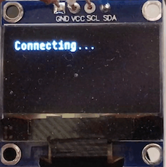
If you watch carefully enough you can see the OLED display transitioning through the various setup steps. Of course, you can also just check the serial output for the full output but that's not nearly as exciting as writing to a display!
You might be thinking, "Ok? I see text but did we actually make a device that other things can find?" Yes, yes we did! We can use a tool like SSDPy to query our device:
pip install ssdpy
ssdpy-discover urn:schemas-upnp-org:device:ahfan:1

{'cache-control': 'max-age=1200',
 'ext': '',
 'location': 'http://192.168.0.45:80/description.xml',
 'server': 'Arduino/1.0 UPNP/1.1 Smart Fan/1',
 'st': 'urn:schemas-upnp-org:device:ahfan:1',
 'usn': 'uuid:38323636-4558-4dda-9188-cda0e67ab9a3'}
You don't have to query the device specifically, you could do ssdpy-discover ssdp:all but you'll probably get a lot more results.
Now that we have a simple shell with most of the useful bits we need, let's start on the actual fan controller. Coming soon in part 2!